MELSEC Q Series / iQ Analog Input Modules
-
Address
C-188, Sector 31-D, P&T Society,
Korangi Industrial Area,
Karachi-74900,
Pakistan
-
Call us on
+92-21-35070751
+92-300-5776703
-
- You are here:
-
Home

- Projects
Projects
Mitsubishi Analog I/O Modules
Analog input modules provide an interface to the CPU for sensing variable real world levels of voltage and current signals. These signals are converted into digital values by the modules for use in programs. This enables the CPU to process variable signals such as pressure, speed & flow. For modules able to sense temperature, please refer to the Temperature Input modules section.
Key Features:
- Module set-up via menus in GX Developer; no programming required (requires use of GX Configurator-AD plug in)
- GX Configurator-AD reduces maintenance time with clear presentation of module status
- Voltage & current inputs, or exclusively voltage or current input
- 4 and 8 channel input versions
- Fast conversion (80 microseconds/channel)
- High accuracy (± 0.1%)
- High resolution (1 part in ±16,000 or 14 bits)
- Switchable resolution (1 part in ±4000, 1 part in ±12,000 & 1 part in ±16,000)
- Averaging function
- Module temperature drift compensation
- Maximum and minimum value hold
Required Manual
|
Model Number |
Description |
Contents |
Included? |
Stocked Item |
|
SH(NA)080055 |
Analog-Digital Converter Module User’s Manual |
Covers Q64AD, Q68ADV, Q68ADI & GX Configurator-AD |
Supplied as PDF with GX Configurator-AD |
- |
|
IB(NA)0800034E |
Analog-Digital (Converter Module User’s Manual (Hardware) |
Basic Information on Q64AD, Q68ADV, Q68ADI |
Yes |
- |
Note: Many of these manuals are available by free download from our website, www.meau.com
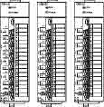
Analog to Digital Converter Modules
|
Model Number |
Q64AD |
Q68ADV |
Q68ADI |
|||||||||||||||||||||||||||||||||||||||||||||||||||||||
|
Stocked Item |
S |
S |
S |
|||||||||||||||||||||||||||||||||||||||||||||||||||||||
|
Certification |
UL • cUL • CE |
UL • cUL • CE |
UL • cUL • CE |
|||||||||||||||||||||||||||||||||||||||||||||||||||||||
|
Number of Analog Input Points |
4 points (4 channels) |
8 points (8 channels) |
8 points (8 channels) |
|||||||||||||||||||||||||||||||||||||||||||||||||||||||
|
Analog Input |
Voltage |
-10 to 10VDC (input resistance value 1MO) |
- |
|||||||||||||||||||||||||||||||||||||||||||||||||||||||
|
Current |
0 to 20mADC (input resistance value 250O) |
- |
0 to 20mADC (input resistance value 250O) |
|||||||||||||||||||||||||||||||||||||||||||||||||||||||
|
Digital Output |
16-bit signed binary (Normal resolution mode: -4096 to 4095, high resolution mode: -12288 to 12287, -16384 to 16383 |
|||||||||||||||||||||||||||||||||||||||||||||||||||||||||
|
I/O Characteristics Max. Resolution |
|
|||||||||||||||||||||||||||||||||||||||||||||||||||||||||
|
Accuracy (Accuracy of Digital Output Value Relative to Maximum Value) (*1) |
|
|||||||||||||||||||||||||||||||||||||||||||||||||||||||||
|
Conversion Time |
80 µs/channel (When temperature drift compensation is provided, time is 160 µs longer, regardless of the number of channels used.) |
|||||||||||||||||||||||||||||||||||||||||||||||||||||||||
|
Absolute Max. Input |
Voltage: ±15V, current: ±30mA |
|||||||||||||||||||||||||||||||||||||||||||||||||||||||||
|
Insulation System |
Across I/O terminals and PLC power supply: Photocoupler insulation; Across channels: No insulation |
|||||||||||||||||||||||||||||||||||||||||||||||||||||||||
|
I/O Device Points Occupied |
16 points (I/O allocation: 16 intelligent points) |
|||||||||||||||||||||||||||||||||||||||||||||||||||||||||
|
Connection Terminal |
18-point terminal block |
|||||||||||||||||||||||||||||||||||||||||||||||||||||||||
|
Internal Current Consumption (5VDC) (A) |
0.63 |
0.64 |
0.64 |
|||||||||||||||||||||||||||||||||||||||||||||||||||||||
|
Weight (kg) |
0.18 |
0.19 |
0.19 |
|||||||||||||||||||||||||||||||||||||||||||||||||||||||
|
Base Unit Slots Occupied |
1 |
|||||||||||||||||||||||||||||||||||||||||||||||||||||||||
Notes:
- “Digit” indicates a digital value. ±4 digit means that the digital value 1000 will vary between 996 and 1004.
MELSEC Q Series / iQ Isolated Analog Modules
For some applications, it is essential that there is channel-to-channel isolation between analog inputs or outputs. These modules provide galvanic isolation between each channel so there is no common connection from one channel to any other.
Required Manuals
|
Model Number |
Description |
Contents |
Included? |
Stocked Item |
|
SH(NA)080277 |
Channel Isolated High Resolution Analog-Digital Converter Module User’s Manual |
Covers Q64AD-GH, Q62AD-DGH & GX Configurator-AD |
Supplied as PDF with GX Configurator-AD |
S |
|
IB(NA)0800223 |
Q64AD-GH Channel Isolated High Resolution Analog-Digital Converter Module |
Basic information on Q64AD-GH |
Yes |
S |
8 CH Analog Module (Isolated Analog)
|
Model Number |
Q68AD-G |
||||||||||||||||||||||||||||||||||||||||||||||||||||||||||||
|
Stocked Item |
S |
||||||||||||||||||||||||||||||||||||||||||||||||||||||||||||
|
Certification |
UL • cUL • CE |
||||||||||||||||||||||||||||||||||||||||||||||||||||||||||||
|
Number of Analog Inputs |
8 points (8 channels) |
||||||||||||||||||||||||||||||||||||||||||||||||||||||||||||
|
Digital Output |
16-bit signed binary (normal resolution mode: -4096 to 4095, high resolution mode: -12288 to 12287, -16384 to 16383) |
||||||||||||||||||||||||||||||||||||||||||||||||||||||||||||
|
Analog Input |
Voltage |
-10 to 10VDC (Input impedance 1OM or more) |
|||||||||||||||||||||||||||||||||||||||||||||||||||||||||||
|
Current |
0 to 20mADC (Input resistance 250O) |
||||||||||||||||||||||||||||||||||||||||||||||||||||||||||||
|
I/O Characteristics Maximum Resolution |
|
||||||||||||||||||||||||||||||||||||||||||||||||||||||||||||
|
Accuracy (Accuracy Relative to Maximum Analog Output Value) |
Reference Accuracy (*1) |
±0.1%; Normal resolution mode : ±4digit (*2); High resolution mode (0 to 10V, -10 to 10V): ±16digit (*2) High resolution mode (Other than the above ranges): ±12digit (*2) |
|||||||||||||||||||||||||||||||||||||||||||||||||||||||||||
|
Temp. Coefficient (*3) |
±71.4ppm/°C (0.00714%/°C) |
||||||||||||||||||||||||||||||||||||||||||||||||||||||||||||
|
Conversion Speed |
10ms / channel |
||||||||||||||||||||||||||||||||||||||||||||||||||||||||||||
|
I/O Device Points Occupied |
16 points |
||||||||||||||||||||||||||||||||||||||||||||||||||||||||||||
|
Isolation Specifications |
|
||||||||||||||||||||||||||||||||||||||||||||||||||||||||||||
|
Connector Type |
A6CON1 or A6CON4 |
||||||||||||||||||||||||||||||||||||||||||||||||||||||||||||
|
Internal Current Consumption (5VDC) |
0.46A |
||||||||||||||||||||||||||||||||||||||||||||||||||||||||||||
|
Weight (kg) |
0.16 |
||||||||||||||||||||||||||||||||||||||||||||||||||||||||||||
|
Base Unit Slots Occupied |
1 |
||||||||||||||||||||||||||||||||||||||||||||||||||||||||||||
Notes:
- Accuracy of offset/gain setting at ambient temperature
- “digit” indicates a digital value.
- Accuracy per temperature change of 1°C Example: Accuracy when temperature changes from 25 to 30°C ±0.1% (reference accuracy) + 0.00714 %/°C (temperature coefficient) x 5°C (temperature change difference) = 0.1357%
High Resolution Analog Module (Isolated Analog Input Channels)
|
Model Number |
Q64AD-GH |
||||||||||||||||||||||||||||||||||||||||||||||||
|
Stocked Item |
S |
||||||||||||||||||||||||||||||||||||||||||||||||
|
Certification |
UL • cUL • CE |
||||||||||||||||||||||||||||||||||||||||||||||||
|
Number of Analog Input Points |
4 points (4 channels) |
||||||||||||||||||||||||||||||||||||||||||||||||
|
Analog Input |
Voltage |
-10 to 10VDC (Input resistance 1MO) |
|||||||||||||||||||||||||||||||||||||||||||||||
|
Current |
0 to 20 mADC (Input resistance 250O) |
||||||||||||||||||||||||||||||||||||||||||||||||
|
Digital Output |
16-bit signed binary (-32768 to 32768); 32-bit signed binary (-65536 to 65536) |
||||||||||||||||||||||||||||||||||||||||||||||||
|
I/O Characteristics Maximum Resolution |
|
||||||||||||||||||||||||||||||||||||||||||||||||
|
Accuracy (Accuracy Relative to Full-Scale) |
Reference Accuracy (*1) |
±0.05%; Digital output value( 32 bit): ±32 digit (*2); Digital output value (16 bit): ±16 digit (*2) |
|||||||||||||||||||||||||||||||||||||||||||||||
|
Temp. Coefficient (*3) |
±71.4 ppm / °C (0.00714% / °C) |
||||||||||||||||||||||||||||||||||||||||||||||||
|
Conversion Speed |
10ms / 4 channels |
||||||||||||||||||||||||||||||||||||||||||||||||
|
Absolute Maximum Input |
Voltage: ± 15V; Current: ± 30mA |
||||||||||||||||||||||||||||||||||||||||||||||||
|
Withstanding Voltage Isolation Method |
Between I/O terminal and PLC power supply: Photocoupler insulation; Between analog input channels: transformer isolation |
||||||||||||||||||||||||||||||||||||||||||||||||
|
Dielectric Strength |
1780VAC ms / 3 cycles (elevation 2000m) |
||||||||||||||||||||||||||||||||||||||||||||||||
|
Isolation Voltage |
Between I/O terminal and PLC power supply: 500VDC 20MO more |
||||||||||||||||||||||||||||||||||||||||||||||||
|
I/O Device Points Occupied |
16 points |
||||||||||||||||||||||||||||||||||||||||||||||||
|
Connected Terminal |
18 points terminal block |
||||||||||||||||||||||||||||||||||||||||||||||||
|
Applicable Solderless Terminals |
R1.25-3 (A solderless terminals with sleeves cannot be used) |
||||||||||||||||||||||||||||||||||||||||||||||||
|
Internal Current Consumption (5VDC) |
0.89 A |
||||||||||||||||||||||||||||||||||||||||||||||||
|
Weight (kg) |
0.20 |
||||||||||||||||||||||||||||||||||||||||||||||||
|
Base Unit Slots Occupied |
1 |
||||||||||||||||||||||||||||||||||||||||||||||||
Notes:
- Accuracy when consistent at some temperature within the ambient temperature (to 55°C)
- “Digit” indicates a digital output value.
- Accuracy per temperature change of 1°C. Example: Accuracy when temperature change from 25 to 30°C. 0.05% (reference accuracy + 0.00714% / °C (temperature coefficient) x 5 °C (temperature change difference) = 0.0857%
Isolated Analog Input Module with Signal Conditioning Function
Required Manuals
|
Model Number |
Description |
Contents |
Included? |
Stocked Item |
|
SH(NA)080277 |
Channel Isolated High Resolution Analog-Digital Converter Module User’s Manual |
Covers Q64AD-GH, Q62AD-DGH & GX Configurator-AD |
Supplied as PDF with GX Configurator-AD |
- |
|
IB(NA)0800224 |
Channel Isolated High Resolution Analog-Digital Converter Module (with Signal Conditioning Function) |
Basic information on Q62AD-DGH |
Yes |
- |
Isolated Analog Input Module with Signal Conditioning Function
|
Model Number |
Q66AD-DG |
||||||||||||||||||||||||||||||
|
Stocked Item |
S |
||||||||||||||||||||||||||||||
|
Certification |
UL • cUL • CE |
||||||||||||||||||||||||||||||
|
Connecting Section with 2-Wire Transmitter |
Input Specification |
Number of Analog Input |
6 points (6 channels) |
||||||||||||||||||||||||||||
|
Analog Input |
4 to 20 mADC (Input resistance 250O) |
||||||||||||||||||||||||||||||
|
Supply Power Specification |
Supply Voltage |
26 ±2VDC |
|||||||||||||||||||||||||||||
|
Maximum Supply Current |
24mADC |
||||||||||||||||||||||||||||||
|
Short-Circuit Protection |
Available; Limit current: 25 to 35mA |
||||||||||||||||||||||||||||||
|
Check Terminals |
Available |
||||||||||||||||||||||||||||||
|
Digital Output |
16-bit signed binary (normal resolution mode: -96 to 4095, high resolution mode: -288 to 12287) |
||||||||||||||||||||||||||||||
|
I/O Characteristics Maximum Resolution |
|
||||||||||||||||||||||||||||||
|
Accuracy (Accuracy Relative to Full-Scale) |
Reference Accuracy (*1) |
±0.1% (Normal resolution mode: ±4digit (*2) High resolution mode: ±12digit (*2)) |
|||||||||||||||||||||||||||||
|
Temp. Coefficient (*3) |
±71.4 ppm / °C (0.00714% / °C) |
||||||||||||||||||||||||||||||
|
Conversion Speed |
10ms / channel |
||||||||||||||||||||||||||||||
|
Insulation |
|
||||||||||||||||||||||||||||||
|
I/O Device Points Occupied |
16 points |
||||||||||||||||||||||||||||||
|
Connected Terminal |
18 points terminal block |
||||||||||||||||||||||||||||||
|
Connector Type |
A6CON4 |
||||||||||||||||||||||||||||||
|
Internal Current Consumption (5VDC) |
0.42 A |
||||||||||||||||||||||||||||||
|
External Power Supply |
24VDC +20%, -15%; Ripple, spike within 500mVp-p; Inrush current: 5.0A, within 400µs; 0.36A |
||||||||||||||||||||||||||||||
|
Weight (kg) |
0.22 |
||||||||||||||||||||||||||||||
|
Base Unit Slots Occupied |
1 |
||||||||||||||||||||||||||||||
Notes:
- Accuracy of offset/gain setting at ambient temperature
- “digit” indicates a digital value.
- Accuracy per temperature change of 1°C. Example: Accuracy when temperature changes from 25 to 30°C 0.1% (reference accuracy) + 0.00714 % / °C (temperature coefficient) x 5°C (temperature change difference) = 0.1357%
High Resolution Isolated Analog Input Module with Signal Conditioning Function
|
Model Number |
Q62AD-DGH |
||||||||||||||||||||
|
Stocked Item |
S |
||||||||||||||||||||
|
Certification |
CE |
||||||||||||||||||||
|
Connecting Section With 2-Wire Transmitter |
Input Specification |
Number of Analog Input |
2 points (2 channels) |
||||||||||||||||||
|
Analog Input |
4 to 20 mADC (*1) (Input resistance 250O) |
||||||||||||||||||||
|
Supply Power Specification |
Supply Voltage |
26 ±2VDC |
|||||||||||||||||||
|
Maximum Supply Current |
24mADC |
||||||||||||||||||||
|
Short-Circuit Protection |
Available; Limit current: 25 to 35mA |
||||||||||||||||||||
|
Check Terminals |
Available |
||||||||||||||||||||
|
Digital Output |
16-bit signed binary (-768 to 32767); 32-bit signed binary (-1538 to 65535) |
||||||||||||||||||||
|
I/O Characteristics Maximum Resolution |
|
||||||||||||||||||||
|
Accuracy (Accuracy Relative to Full-Scale) |
Reference Accuracy (*2) |
±0.05%; Digital output value( 32 bit): ±32 digit (*3); Digital output value (16 bit): ±16 digit (*3) |
|||||||||||||||||||
|
Temp. Coefficient (*4) |
±71.4 ppm / °C (0.00714% / °C) |
||||||||||||||||||||
|
Conversion Speed |
10ms / 2 channels |
||||||||||||||||||||
|
Insulation |
|
||||||||||||||||||||
|
I/O Device Points Occupied |
16 points |
||||||||||||||||||||
|
Connected Terminal |
18 points terminal block |
||||||||||||||||||||
|
Applicable Solderless Terminals |
R1.25-3 (A solderless terminals with sleeves cannot be used) |
||||||||||||||||||||
|
Internal Current Consumption (5VDC) |
0.33 A |
||||||||||||||||||||
|
External Power Supply |
24VDC +20%, -15%; Ripple, spike within 500mVp-p; Inrush current: 5.5A, within 200µs; 0.19A |
||||||||||||||||||||
|
Weight (kg) |
0.19 |
||||||||||||||||||||
|
Base Unit Slots Occupied |
1 |
||||||||||||||||||||
Notes:
- User range setting is 2 to 24mA
- Accuracy of offset/gain setting at ambient temperature. Q62AD-DGH needs to be powered on 30 minutes prior to operation for compliance to the specification (accuracy)
- “Digit” indicates a digital output value.
- Accuracy per temperature change of 1°C.
Example: Accuracy when temperature change from 25 to 30°C. 0.05% (reference accuracy + 0.00714% / °C (temperature coefficient) x 5 °C (temperature change difference) = 0.0857%
MELSEC Q Series / iQ Combination Analog Module
|
Model Number |
Q64AD2DA |
||||||||||||||||||||||||||||||||||||||||||||||||||||
|
Stocked Item |
S |
||||||||||||||||||||||||||||||||||||||||||||||||||||
|
Certification |
UL • cUL • CE |
||||||||||||||||||||||||||||||||||||||||||||||||||||
|
Number of Analog Input Points |
4 points (4 channels) |
||||||||||||||||||||||||||||||||||||||||||||||||||||
|
Analog Input |
Voltage |
-10 to 10VDC (input resistance value 1MO) |
|||||||||||||||||||||||||||||||||||||||||||||||||||
|
Current |
0 to 20mADC (input resistance value 250O) |
||||||||||||||||||||||||||||||||||||||||||||||||||||
|
Digital Output |
Normal resolution mode:-96 to 4095, -4096 to 4095, -1096 to 4595 High resolution mode:-384 to 16383, -288 to 12287, -16384 to 16383, -3288 to 13787 |
||||||||||||||||||||||||||||||||||||||||||||||||||||
|
I/O Characteristics Max. Resolution |
|
||||||||||||||||||||||||||||||||||||||||||||||||||||
|
Accuracy (Accuracy of Digital Output Value Relative to Maximum Value) (*1) |
|
||||||||||||||||||||||||||||||||||||||||||||||||||||
|
Conversion Time |
500 µs/channel |
||||||||||||||||||||||||||||||||||||||||||||||||||||
|
Absolute Max. Input |
Voltage: ±15V, current: ±30mA (*2) |
||||||||||||||||||||||||||||||||||||||||||||||||||||
|
Number Of Analog Output Points |
2 points (2 channels) |
||||||||||||||||||||||||||||||||||||||||||||||||||||
|
Digital Input |
Normal resolution mode: -96 to 4095, -4096 to 4095; High resolution mode: -288 to 12287, -16384 to 16383 |
||||||||||||||||||||||||||||||||||||||||||||||||||||
|
Analog Output |
Voltage |
-10 to 10VDC (External load resistance: 1MO) |
|||||||||||||||||||||||||||||||||||||||||||||||||||
|
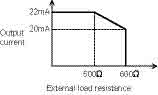
Current |
0 to 20mADC (External load resistance: 600O) |
||||||||||||||||||||||||||||||||||||||||||||||||||||
|
I/O Characteristics Maximum Resolution |
|
||||||||||||||||||||||||||||||||||||||||||||||||||||
|
Accuracy (Accuracy With Respect To Maximum Analog Output Value) |
|
||||||||||||||||||||||||||||||||||||||||||||||||||||
|
Conversion Speed |
500 µs/channel |
||||||||||||||||||||||||||||||||||||||||||||||||||||
|
Absolute Maximum Output |
Voltage: 12V Current: 21mA |
||||||||||||||||||||||||||||||||||||||||||||||||||||
|
Output Short Circuit Protection |
Available |
||||||||||||||||||||||||||||||||||||||||||||||||||||
|
I/O Device Points Occupied |
16 points (I/O assignment: Intelligent 16 points) |
||||||||||||||||||||||||||||||||||||||||||||||||||||
|
Connected Terminals |
18 points terminal block |
||||||||||||||||||||||||||||||||||||||||||||||||||||
|
Applicable Solderless Terminal |
A/D conversion part, D/A conversion part: R1.25-3 (Solderless terminals with sleeves are unavailable.) External power supply 24VDC, FG terminal connection: Not available |
||||||||||||||||||||||||||||||||||||||||||||||||||||
|
External Supply Power |
24VDC 15%; Ripple, spike 500mVP-P or less; Inrush current: 2.5A 150µs or less; Current consumption: 0.19A |
||||||||||||||||||||||||||||||||||||||||||||||||||||
|
Internal Current Consumption (5VDC) |
0.17A |
||||||||||||||||||||||||||||||||||||||||||||||||||||
|
Weight (kg) |
0.23 |
||||||||||||||||||||||||||||||||||||||||||||||||||||
|
Base Unit Slots Occupied |
1 |
||||||||||||||||||||||||||||||||||||||||||||||||||||
Notes:
- A1: The selection ranges and accuracies have the following relationships.
Ambient Temperature
Temperature Range
Pt100 and JPt100 : -20 to 120°C
Pt100 : -200 to 850°C
JPt100 : -180 to 600°C
0 to 55°C
±0.3°C
±2.125°C
±1.5°C
25 ±5°C
±0.096°C
±0.68°C
±0.48°C
The conversion speed is a period from when a temperature is input and converted into a corresponding digital value until the value is stored into the buffer memory. When two or more channels are used, the conversion speed is “40ms number of conversion enabled channels”. - For output in the case of disconnection detection, select any of “Value immediately before disconnection”, “Up scale (maximum value of measured temperature range + 5% of measured temperature range)”, “Down scale (minimum value of measured temperature range - 5% of measured temperature range)” or “Given value”.
MELSEC Q Series / iQ Analog Output Modules
Analog output modules allow the CPU to convert digital program values to real world analog current or voltage signals. These can then be used to control actuators whose properties vary between set limits, such as valve openings, speed control, extension distance, etc.
Key Features:
- Module set-up via menus in GX Developer; no programming required (requires use of GX Configurator-DA plug in)
- GX Configurator-DA reduces maintenance time with clear presentation of module status
- 2, 4 & 8 channel versions
- Fast conversion (80 microseconds/channel)
- High accuracy (±0.1%)
- High resolution (1 part in ±16,000 or 14 bits)
- Switchable resolution (1 part in ±4000, 1 part in ±12,000 and 1 part in ±16,000)
- Variable offset/gain
- Synchronous output function establishes output changes on a set timebase
- Output hold/clear function
- Output test when CPU is in STOP mode
Required Manuals
|
Model Number |
Description |
Contents |
Included? |
Stocked Item |
|
SH(NA)080054 |
Digital-Analog Converter Module User’s Manual |
Covers Q62DAN, Q64DAN, Q68DAVN, Q68DAIN GX Configurator-DA |
Supplied as PDF with GX Configurator-DA |
- |
|
IB(NA)0800321E |
D/A Converter Module Users’ Manual (Hardware) |
Basic information on Q62DAN, Q64DAN, Q68DAVN, Q68DAIN |
Yes |
- |
Note: Many of these manuals are available by free download from our website, www.meau.com
|
Model Name |
Q62DAN |
Q64DAN |
Q68DAVN |
Q68DAIN |
|||||||||||||||||||||||||||||||||||||||||||||
|
Stocked Item |
S |
S |
S |
S |
|||||||||||||||||||||||||||||||||||||||||||||
|
Number Of Analog Output Points |
2 points (2 channels) |
4 points (4 channels) |
8 points (8 channels) |
||||||||||||||||||||||||||||||||||||||||||||||
|
Digital Input |
16-bit signed binary (normal resolution mode: -4096 to 4095, High resolution mode: -12288 to 12287, -16384 to 16383) |
||||||||||||||||||||||||||||||||||||||||||||||||
|
Analog Output |
Voltage |
-10 to 10VDC (External load resistance value: 1KO to 1MO) |
- |
||||||||||||||||||||||||||||||||||||||||||||||
|
Current |
0 to 20 mA DC (External load resistance value: 0O to 600O) |
- |
0 to 20 mA DC (External load resistance value: 0O to 600O) |
||||||||||||||||||||||||||||||||||||||||||||||
|
I/O Characteristics, Maximum Resolution |
|
||||||||||||||||||||||||||||||||||||||||||||||||
|
Accuracy (Accuracy With Respect To Maximum Analog Output Value) |
Ambient Temp. 25 ±5°C |
Within ± 0.1 % (Voltage: ±10 mV, Current: ± 20µA) |
|||||||||||||||||||||||||||||||||||||||||||||||
|
Ambient Temp. 0 to 55°C |
Within ± 0.3 % (Voltage: ± 30 mV, Current: ± 60µA) |
||||||||||||||||||||||||||||||||||||||||||||||||
|
Conversion Speed |
80µs/channel |
||||||||||||||||||||||||||||||||||||||||||||||||
|
Output Short Circuit Protection |
Available |
||||||||||||||||||||||||||||||||||||||||||||||||
|
I/O Device Points Occupied |
16 points (I/O assignment: Intelligent 16 points) |
||||||||||||||||||||||||||||||||||||||||||||||||
|
Connected Terminals |
18-points terminal block |
||||||||||||||||||||||||||||||||||||||||||||||||
|
Applicable Solderless Terminal |
R1.25-3 (A solderless terminal with sleeve cannot be used) |
FG terminal: R1.25-3, 1.25-YS3, RAV1.25-3, V1.25-YS3A; Other terminals than FG: R1.25-3 (A solderless terminal with sleeve cannot be used) |
|||||||||||||||||||||||||||||||||||||||||||||||
|
External Supply Power |
24VDC + 20 %, -15 % |
||||||||||||||||||||||||||||||||||||||||||||||||
|
Ripple, spike 500 mV P-P or less |
|||||||||||||||||||||||||||||||||||||||||||||||||
|
Inrush current: 2.5 A, within 250µs |
Inrush current: 2.5 A, within 260µs |
Inrush current: 2.5 A, within 230µs |
Inrush current: 2.5 A, within 230µs |
||||||||||||||||||||||||||||||||||||||||||||||
|
0.15 A |
0.24 A |
0.20 A |
0.27 A |
||||||||||||||||||||||||||||||||||||||||||||||
|
Internal Current Consumption (5VDC) |
0.33 A |
0.34 A |
0.38 A |
0.38 A |
|||||||||||||||||||||||||||||||||||||||||||||
|
Weight (kg) |
0.19 |
0.20 |
0.20 |
0.20 |
|||||||||||||||||||||||||||||||||||||||||||||
|
Base Unit Slots Occupied |
1 |
||||||||||||||||||||||||||||||||||||||||||||||||
Isolated Analog Output Modules with Output Monitor
|
Model Number |
Q62DA-FG |
|||||||||||||||||||||||||||||
|
Stocked Item |
S |
|||||||||||||||||||||||||||||
|
Certification |
UL • cUL • CE |
|||||||||||||||||||||||||||||
|
Number of Analog Outputs |
2 points (2 channels) |
|||||||||||||||||||||||||||||
|
Digital Input |
16-bit signed binary (-12288 to 12287, -16384 to 16383) |
|||||||||||||||||||||||||||||
|
Analog Output |
Voltage |
-12 to 12VDC (External load resistance 1k to 1MO) |
||||||||||||||||||||||||||||
|
Current |
0 to 20 mADC (External load resistance: 0 to 600O); 0 to 22 mADC |
|||||||||||||||||||||||||||||
|
I/O Characteristics Maximum Resolution |
|
|||||||||||||||||||||||||||||
|
Accuracy (Accuracy Relative to Maximum Analog Output Value) |
Reference Accuracy (*1) |
within ±0.1%; (Voltage: ±10mV, Current: ±20µA) |
||||||||||||||||||||||||||||
|
Temp. Coefficient (*2) |
±80 ppm / °C (0.008% / °C) |
|||||||||||||||||||||||||||||
|
Conversion Speed |
10ms / 2 channels |
|||||||||||||||||||||||||||||
|
Output Monitor |
Resolution |
12 bit |
||||||||||||||||||||||||||||
|
Reference Accuracy (*1) |
±0.2% |
|||||||||||||||||||||||||||||
|
Temperature Coefficient (*2) |
±160ppm / °C (0.016% / °C) |
|||||||||||||||||||||||||||||
|
Output Short-Circuit Protection |
Available |
|||||||||||||||||||||||||||||
|
I/O Device Points Occupied |
16 points |
|||||||||||||||||||||||||||||
|
Isolation Specifications |
|
|||||||||||||||||||||||||||||
|
Connected Terminal |
18 points terminal block |
|||||||||||||||||||||||||||||
|
Applicable Solderless Terminals |
R1.25-3 (A solderless terminals with sleeves cannot be used) |
|||||||||||||||||||||||||||||
|
Internal Current Consumption (5VDC) |
0.37A |
|||||||||||||||||||||||||||||
|
External Power Supply |
24VDC +20%, -15%; Ripple, spike within 500mVp-p; Inrush current: 5.2A, within 300µs, 0.3A |
|||||||||||||||||||||||||||||
|
Weight (kg) |
0.20 |
|||||||||||||||||||||||||||||
|
Base Unit Slots Occupied |
1 |
|||||||||||||||||||||||||||||
Notes:
- Accuracy of offset/gain setting at ambient temperature Q62AD-DGH needs to be powered on 30 minutes prior to operation for compliance to the specification (accuracy).
- Accuracy per temperature change of 1°C.
Example: Accuracy when temperature change from 25 to 30°C. 0.1% (reference accuracy + 0.008% / °C (temperature coefficient) x 5 °C (temperature change difference) = 0.14%
|
Model Number |
Q66DA-G |
|||||||||||||||||||||||||||||||||||||||||||||||||
|
Stocked Item |
S |
|||||||||||||||||||||||||||||||||||||||||||||||||
|
Certification |
UL • cUL • CE |
|||||||||||||||||||||||||||||||||||||||||||||||||
|
Number of Analog Outputs |
6 points (6 channels) |
|||||||||||||||||||||||||||||||||||||||||||||||||
|
Digital Input |
16-bit signed binary (normal resolution mode:-4096 to 4095; high resolution mode: -12288 to 12287, -16384 to 16383) |
|||||||||||||||||||||||||||||||||||||||||||||||||
|
Analog Output |
Voltage |
-12 to 12VDC (External load resistance 1k to 1MO) |
||||||||||||||||||||||||||||||||||||||||||||||||
|
Current |
0 to 20 mADC (External load resistance: 0 to 600O); 0 to 22 mADC (External load resistance: Please refer to Note 3) |
|||||||||||||||||||||||||||||||||||||||||||||||||
|
I/O Characteristics Maximum Resolution |
|
|||||||||||||||||||||||||||||||||||||||||||||||||
|
Accuracy (Accuracy Relative to Maximum Analog Output Value) |
Reference Accuracy (*1) |
within ±0.1%; (Voltage: ±10mV, Current: ±20µA) |
||||||||||||||||||||||||||||||||||||||||||||||||
|
Temp. Coefficient (*2) |
±80 ppm / °C (0.008% / °C) |
|||||||||||||||||||||||||||||||||||||||||||||||||
|
Conversion Speed |
6ms / channels |
|||||||||||||||||||||||||||||||||||||||||||||||||
|
Output Monitor |
Resolution |
15-bit |
||||||||||||||||||||||||||||||||||||||||||||||||
|
Reference Accuracy (*1) |
±0.1% |
|||||||||||||||||||||||||||||||||||||||||||||||||
|
Temperature Coefficient (*2) |
0.008% / °C |
|||||||||||||||||||||||||||||||||||||||||||||||||
|
Output Short-Circuit Protection |
Available |
|||||||||||||||||||||||||||||||||||||||||||||||||
|
I/O Device Points Occupied |
16 points |
|||||||||||||||||||||||||||||||||||||||||||||||||
|
Isolation Specifications |
|
|||||||||||||||||||||||||||||||||||||||||||||||||
|
Connected Terminal |
40-pin connector |
|||||||||||||||||||||||||||||||||||||||||||||||||
|
Applicable Solderless Terminals |
R1.25-3 (A solderless terminals with sleeves cannot be used) |
|||||||||||||||||||||||||||||||||||||||||||||||||
|
Internal Current Consumption (5VDC) |
0.62A |
|||||||||||||||||||||||||||||||||||||||||||||||||
|
External Power Supply |
24VDC, +20%, -15%; Ripple, spike within 500 mV p-p; Inrush current: 4.8A, within 400µs; 0.22A |
|||||||||||||||||||||||||||||||||||||||||||||||||
|
Weight (kg) |
0.22 |
|||||||||||||||||||||||||||||||||||||||||||||||||
|
Base Unit Slots Occupied |
1 |
|||||||||||||||||||||||||||||||||||||||||||||||||
Notes:
- Accuracy of offset/gain setting at ambient temperature Q66DA-G needs to be powered on 30 minutes prior to operation for compliance to the specification (accuracy).
- Accuracy per temperature change of 1 °C
Example: Accuracy when temperature changes from 25 to 30 °C
0.1% (Reference accuracy) + 0.008%/ °C (temperature coefficient) x 5 °C (temperature change difference) = 0.14% - The following indicates the external load resistance when output current is 20mA or more.
Q Series/iQ HART Interface Module
The Q Series HART® Interface I/O Modules provide total access to process data and device diagnostics from over 1000 HART enabled field devices. The system is designed to use the 4-20mA (or 0-20mA) control signal from traditional analog devices as well as the 4-20mA and digital process data from HART devices, allowing up to 5 (1 analog, 4 digital process variables) control points on a single 2-wire connection.
Key Features:
- 8 channel 4-20mA I/O modules (traditional or HART enabled 4-20mA devices), up to 512 channels on a single Process CPU
- HART Digital Communications combines high speed control (4-20mA) with access to multivariable process data
- Compatible with HART revisions 5, 6 and 7
- Configuration of field devices via an industry standard FDT frame application
- Reduces integration time and device setup through standardized interfaces
|
Model Number |
ME1AD8HAI-Q |
|||||||||
|
Stocked Item |
- |
|||||||||
|
Number of Analog Input Points |
8 points (8 channels) |
|||||||||
|
Analog Input |
Current |
0 to 20 mA DC • 4 to 20 mA DC |
||||||||
|
Absolute Maximum Input |
± 30 mA |
|||||||||
|
Input Resistance |
250 O |
|||||||||
|
Short-Circuit Protection |
Available |
|||||||||
|
Primary Filter |
Hz (3 dB), HART signal is 1200 Hz with 1 mAP-P |
|||||||||
|
Digital Output |
16-bit signed binary (–768 to 32767) |
|||||||||
|
I/O Characteristics, Maximum Resolution |
|
|||||||||
|
Accuracy (Relative to Digital Output Value) (*1) |
±0.15% (±48 digit) (*2) |
|||||||||
|
Cycle Time |
80 ms (Independent to the number of used channels) |
|||||||||
|
Insulation Method |
Between the I/O Terminals and PLC Power Supply |
Photocoupler insulation |
||||||||
|
Between Analog Input Channels |
Non-insulated |
|||||||||
|
HART Modem |
FSK Physical Layer, multiplexed |
|||||||||
|
HART Functions |
Protocol Revision 6 support • 4 Process variables support (PV, SV, TV, QV) • FDT/DTM support |
|||||||||
|
Number of I/O Occupied Points |
32 points (I/O assignment: Intelligent 32 points) |
|||||||||
|
External Wiring Connection System |
18-points terminal block |
|||||||||
|
Applicable Wire Size |
Refer to the HART specification for more details. The external power supply voltage of the ME1AD8HAI-Q should be enough for correct operation of the analog transmitter. (*3, *4) |
|||||||||
|
Applicable Solderless Terminals |
R1.25-3 (Solderless terminals with sleeves cannot be used) |
|||||||||
|
External Supply Power |
Voltage |
24VDC (+20%, -15%); ripple, spike within 500mVP-P |
||||||||
|
Current (A) |
0.3 |
|||||||||
|
Inrush Current |
5.5 A within 200 µs |
|||||||||
|
Online Module Change |
Not supported |
|||||||||
|
Internal Current Consumption (5VDC) (A) |
0.32 |
|||||||||
|
Weight (kg) |
0.19 |
|||||||||
|
Base Unit Slots Occupied |
1 |
|||||||||
Notes:
- ME1AD8HAI-Q needs to be powered on 30 minutes prior to operation for compliance to the specification (accuracy).
- “digit” indicates a digital value.
- Use case:For distances up to 800 m, the wire size of 0.51 mm diameter with 115 nF/km cable capacitance and 36.7 //km cableresistance can be applied.
- Refer to the calculation example shown in section 4.4.2 (External wiring).
Q Series / iQ Load Cell Input Module
|
Model Number |
Q61LD |
||||||||||||||
|
Stocked Item |
S |
||||||||||||||
|
Certification |
UL • cUL • CE |
||||||||||||||
|
Number of Analog Inputs |
1 point (1 channel) |
||||||||||||||
|
Digital Output |
32-bit signed binary; 0 to 10000 |
||||||||||||||
|
Analog Input Range (Load Cell Rated Output) |
0.0 to 1.0mV/V, 0.0 to 2.0mV/V, 0.0 to 3.0mV/V |
||||||||||||||
|
I/O Characteristics Maximum Resolution |
|
||||||||||||||
|
Accuracy (Accuracy Relative to Maximum Analog Output Value) |
Nonlineality: Within ±0.01%/FS (Ambient temperature 25°C); Zero drift: Within ±0.25µV/°C RTI; Gain drift: Within ±15 ppm/°C |
||||||||||||||
|
Conversion Speed |
10ms |
||||||||||||||
|
Accuracy (Accuracy Relative to Analog Input (Load Cell Rated Output) of a Module) |
Nonlineality: Within ±0.01%/FS (Ambient temperature 25°C ); Zero drift: Within ±0.25µV/°C RTI; Gain drift: Within ±15 ppm/°C |
||||||||||||||
|
I/O Device Points Occupied |
16 points |
||||||||||||||
|
Connected Terminal |
18 point terminal block |
||||||||||||||
|
Applicable Solderless Terminals |
R1.25-3 (A solderless terminal cannot be used) |
||||||||||||||
|
Internal Current Consumption (5VDC) |
0.48A |
||||||||||||||
|
External Power Supply |
24VDC +20%, -15%; Ripple, spike within 500mVp-p; Inrush current: 5.2A, within 300µs, 0.3A |
||||||||||||||
|
Weight (kg) |
0.17 |
||||||||||||||
|
Base Unit Slots Occupied |
1 |
||||||||||||||
Mitsubishi Digital I/O Modules & Terminal Blocks
MELSEC Q Series / iQ Digital Input Modules
Digital input modules provide the CPU interface for monitoring on/off voltage signals in your system.
Key Features:
- Sense commonly used AC and DC voltages
- Negative/positive common types
- 16, 32 or 64 inputs per module, depending on module type.
- 1-70ms software selectable input filter response time (via GX Developer) for adjusting input response. This avoids the effects of noise on the inputs
- DC input short circuit protection
- Internal optoisolation
- Removable terminal blocks
- Established A Series connectors (FCN/D-sub type) on 32 & 64 I/O modules for compatibility with existing A Series terminal block (A6TBXY type) installations
If you need to monitor varying signal levels of voltage or current, please refer to the analog input modules section. If you need to monitor digital signals that change their state rapidly (more than approximately 10 Hz, depending on program scan time), then consider using high-speed counter modules.
Q Series / iQ Input Modules
|
Model Number |
QX10 |
QX28 |
QX40 |
QX40-S1 |
QX40H |
QX41 |
QX41-S1 |
|
|
Stocked Item |
S |
- |
S |
S |
- |
S |
- |
|
|
Certification |
UL • cUL • CE |
|||||||
|
Input Type |
AC |
AC |
DC positive common (sink) |
|||||
|
No. of Input Points |
16 |
8 |
16 |
16 |
16 |
32 |
32 |
|
|
Input Voltage |
100-120VAC +10%/-15%, 50/60Hz ±3Hz |
100-240VAC +10%/-15%, 50/60Hz ±3Hz |
24VDC +20%/-15% |
24VDC +20%/ -15%, ripple ratio: within 5% |
24VDC +20%/-15% |
|||
|
Input Current (mA) |
8 |
17 (@200 VAC/60Hz)/ 14 (@200 80@100 VAC/60Hz)/ VAC/50Hz) 7 (100 VAC/50Hz) |
4 |
6 |
4 |
|||
|
Response Time (ms) |
OFF-ON |
15@100VAC, 50/60Hz |
10@100VAC, 50/60Hz |
1/5/10/20/70 (*1) |
0.1/0.2/0.4/0.6/1 (*1) |
.04/.10/.25/ .50/.95 (*1) |
1/5/10/20/70 (*1) |
0.1/0.2/0.4/0.6/1 (*1) |
|
ON-OFF |
20@100VAC, 50/60Hz |
20@100VAC, 50/60Hz |
1/5/10/20/70 (*1) |
0.1/0.2/0.4/0.6/1 (*1) |
.04/.10/.25/ .50/.95 (*1) |
1/5/10/20/70 (*1) |
0.1/0.2/0.4/0.6/1 (*1) |
|
|
Connection Type |
Screw Terminals |
Screw Terminals |
Screw Terminals |
Screw Terminals |
Crimping Terminal |
FCN x 1 (*2) |
FCN x 1 (*2) |
|
|
Points/Common |
16 |
8 |
16 |
16 |
8 |
32 |
32 |
|
|
Maximum 5VDC Current Consumption (mA) |
50 |
50 |
50 |
60 |
80 |
75 |
75 |
|
|
Weight (kg) |
0.17 |
0.2 |
0.16 |
0.2 |
0.16 |
0.15 |
0.15 |
|
|
Base Unit Slots Occupied |
1 |
|||||||
Notes: See below.
|
Model Number |
QX41-S2 |
QX42 |
QX42-S1 |
QX70 |
QX70H |
QX71 |
QX72 |
|
|
Stocked Item |
- |
S |
S |
S |
S |
S |
- |
|
|
Certification |
UL • cUL • CE |
|||||||
|
Input Type |
DC positive common (sink) |
DC positive/negative common (sink/source) |
DC positive/common (sink) |
DC positive/negative common (sink/source) |
||||
|
No. of Input Points |
32 |
64 |
64 |
16 |
16 |
32 |
64 |
|
|
Input Voltage |
24VDC +20%/-15% |
5/12VDC +20%/-15% |
5VDC +20%/-15% |
5/12VDC +20%/-15% |
||||
|
Input Current (mA) |
6 |
4 |
4 |
1.2 / 3.3 |
3 |
1.2 / 3.3 |
1.2 / 3.3 |
|
|
Response Time (ms) |
OFF-ON |
1/5/10/20/70 (*1) |
1/5/10/20/70 (*1) |
0.1/0.2/0.4/0.6/1 (*1) |
1/5/10/20/70 (*1) |
.04/.10/.25/ .50/.95 (*1) |
1/5/10/20/70 (*1) |
|
|
ON-OFF |
1/5/10/20/70 (*1) |
1/5/10/20/70 (*1) |
0.1/0.2/0.4/0.6/1 (*1) |
1/5/10/20/70 (*1) |
.04/.10/.25/ .50/.95 (*1) |
1/5/10/20/70 (* 1) |
||
|
Connection Type |
FCN x 2 (*2) |
FCN x 2 (*2) |
FCN x 2 (*2) |
Screw Terminals |
Crimping Terminal |
FCN x 1 (*2) |
FCN x 2 (*2) |
|
|
Points/Common |
32 |
32 |
32 |
16 |
8 |
32 |
32 |
|
|
Maximum 5VDC Current Consumption (mA) |
75 |
90 |
90 |
55 |
80 |
70 |
85 |
|
|
Weight (kg) |
0.15 |
0.18 |
0.18 |
0.14 |
0.14 |
0.12 |
0.13 |
|
|
Base Unit Slots Occupied |
1 |
|||||||
Notes: See below
MELSEC Q Series / iQ Input Modules(Continued)
|
Model Number |
QX80 |
QX80H |
QX81 |
QX81-S2 |
QX82 |
QX82-S1 |
QX90H |
|
|
Stocked Item |
S |
S |
S |
- |
S |
- |
S |
|
|
Certification |
UL • cUL • CE |
|||||||
|
Input Type |
DC negative common (source) |
|||||||
|
No. of Input Points |
16 |
16 |
32 |
32 |
64 |
64 |
16 |
|
|
Input Voltage |
24VDC +20%/-15% |
24VDC +20%/-15% |
24VDC +20%/-15% |
24VDC (+20/-15%, ripple ratio within 5%) |
24VDC +20%/-15% |
24VDC +20%/-15% |
5VDC +20%/-15% |
|
|
Input Current (mA) |
4 |
6 |
4 |
6 |
4 |
4 |
6 |
|
|
Response Time (ms) |
OFF-ON |
1/5/10/20/70 (*1) |
.04/.10/.25/.50/.95 (*1) |
1/5/10/20/70 (*1) |
.05/.15/.3/.55/1.05 (*1) |
.04/.10/.25/.50/.95 (*1) |
||
|
ON-OFF |
1/5/10/20/70 (*1) |
.04/.10/.25 /.50/.95 (*1) |
1/5/10/20/70 (*1) |
.15/.2/.35/.6/1.1 (*1) |
.04/.10/.25 /.50/.95 (*1) |
|||
|
Minimum On Voltage/Current |
19VDC/3mA |
13V or higher/3mA |
19VDC/3mA |
15VDC/3mA |
19VDC/3mA |
19VDC/3mA |
3.5V or higher/3mA |
|
|
Maximum Off Voltage/Current |
11VDC/ 1.7mA |
8V or lower/1.6mA |
11VDC/ 1.7mA |
5VDC/ 1.7mA |
11VDC/ 1.7mA |
9.5VDC/1.5mA |
1V or lower/1mA |
|
|
Connection Type |
Screw Terminals |
Crimping Terminal |
D-Sub (*3) |
D-Sub |
FCN x 2 (*2) |
FCN x 2 (*2) |
Crimping Terminal |
|
|
Points/Common |
16 |
8 |
32 |
32 |
32 |
32 |
8 |
|
|
Maximum 5VDC Current Consumption (mA) |
50 |
80 |
75 |
75 |
90 |
90 |
80 |
|
|
Weight (kg) |
0.16 |
0.16 |
0.16 |
0.16 |
0.18 |
0.18 |
0.14 |
|
|
Base Unit Slots Occupied |
1 |
|||||||
Notes:
- Set response time by parameters in GX Developer. Default is 10ms (0.2ms for -S1 versions). Input and output response times cannot be set independently.
- 40 pin FCN connector. Supplied separately. See “I/O Wiring Connectors” for ordering information.
- 37 pin D-sub connector. Supplied separately. See “I/O Wiring Connectors” for ordering information.
MELSEC Q Series / iQ Combination I/O Modules
Combination input/output modules allow both input and output points to be combined in a single module. This offers the chance to reduce the number of I/O modules, enabling a more compact system in some applications.
Combination I/O Modules
|
Model Number |
QH42P |
QX41Y41P (*1) |
QX48Y57 |
|
|
Stocked Item |
S |
S |
S |
|
|
Certification |
UL • cUL • CE |
|||
|
Input Type |
DC positive common (sink) |
|||
|
No. of Input Points |
32 |
32 |
8 |
|
|
Input Voltage |
24VDC +20%/-15% |
|||
|
Input Current (mA) |
4 |
|||
|
Response Time (ms) |
OFF-ON |
1/5/10/20/70 (*2) |
||
|
ON-OFF |
1/5/10/20/70 (*2) |
|||
|
Minimum On Voltage/Current |
19VDC/3mA |
|||
|
Maximum Off Voltage/Current |
11VDC/1.7mA |
|||
|
Points/Common |
32 |
32 |
8 |
|
|
Output Type |
Sink transistor |
|||
|
No. of Output Points |
32 |
32 |
7 |
|
|
Load Voltage |
12-24VDC +20%/-15% |
|||
|
Maximum Load Current |
0.1A/pt, 2A/common |
0.1A/pt, 2A/common |
0.5A/pt, 2A/common |
|
|
Response Time (ms) |
OFF-ON |
1 |
||
|
ON-OFF |
1 (rated resistive load) |
|||
|
External Supply Voltage/Current |
12-24VDC +20%/-15%/15mA (24VDC)/common |
|||
|
Protection |
Thermal & short circuit |
Thermal & short circuit |
Fused (4A), with blown fuse detection |
|
|
Points/Common |
32 |
32 |
7 |
|
|
Connection Type |
FCN (*3) |
FCN (*3) |
Screw Terminals |
|
|
Maximum 5VDC Current Consumption (mA) |
130 |
130 |
80 |
|
|
Weight (kg) |
0.2 |
|||
|
Base Unit Slots Occupied |
1 |
|||
Notes:
- The QX41Y41P has consecutive I/O addressing, unlike the QH42P, and is meant to replace A Series I/O blocks.
- Set response time by parameters in GX Developer. Default is 10ms (0.2ms for -S1 versions). Input and output response times cannot be set independently.
- 40 pin FCN connector. Supplied separately. See “I/O Wiring Connectors” for ordering information.
MELSEC Q Series / iQ Digital Output Modules
Digital output modules provide the CPU interface for turning devices in your system on & off under program control.
Key Features:
- Relay (contact), sink & source transistor plus triac outputs to handle all common devices
- 16, 32 or 64 outputs per module, depending on module type
- Thermal & short-circuit protection on some modules
- Internal optoisolation
- Removable terminal blocks
- Established A Series connectors (FCN/D-sub type) on 32 & 64 I/O modules for compatibility with existing A Series terminal block (A6TBXY type) installations
- If you need to produce varying signal levels of voltage or current, please refer to the analog output modules section.
|
Model Number |
QY10 |
QY18A |
QY22 |
QY40P |
QY41P |
QY42P |
|
|
Stocked Item |
S |
S |
S |
S |
S |
S |
|
|
Certification |
UL • cUL • CE |
UL • cUL • CE |
UL • cUL • CE |
UL • cUL • CE |
UL • cUL • CE |
UL • cUL • CE |
|
|
Output Type |
Relay |
Isolated Relay |
Triac |
Sink Transistor |
Sink Transistor |
Sink Transistor |
|
|
No. of Output Points |
16 |
8 |
16 |
16 |
32 |
64 |
|
|
Load Voltage |
24VDC/240VAC |
24VDC/240VAC |
100-240VAC, +5% |
12-24VDC, +20/-15% |
12-24VDC, +20/-15% |
12-24VDC, +20/-15% |
|
|
Maximum Load Current |
2A/pt, 8A/common |
2A/point |
0.6A/pt, 4.8A/common |
0.1A/pt, 1.6A/common |
0.1A/pt, 2.0A/common |
0.1A/pt, 2.0A/common |
|
|
Response Time (ms) |
OFF-ON |
10 |
10 |
1 |
1 |
1 |
1 |
|
ON-OFF |
12 |
12 |
1ms+0.5 cycle (rated resistive load) |
1 (rated resistive load) |
1 (rated resistive load) |
1 (rated resistive load) |
|
|
External Supply Voltage/Current |
N/A |
N/A |
N/A |
12-24VDC (+20/-15%) 10mA |
12-24VDC (+20/-15%) 10mA |
12-24VDC (+20/-15%) 10mA |
|
|
Protection |
N/A; use surge suppressor |
N/A; use surge suppressor |
RC surge suppressor |
Thermal & short-circuit |
Thermal & short-circuit |
Thermal & short-circuit |
|
|
Points/Common |
16 |
All points interdependent |
16 |
16 |
32 |
64 |
|
|
Connection Type |
Screw Terminal |
Screw Terminal |
Screw Terminal |
Screw Terminal |
FCN (*1) |
FCN x 2 (*1) |
|
|
Maximum 5VDC Current Consumption (mA) |
430 |
240 |
250 |
65 |
105 |
150 |
|
|
Weight (kg) |
0.22 |
0.22 |
0.4 |
0.16 |
0.15 |
0.17 |
|
|
Base Unit Slots Occupied |
1 |
||||||
|
Model Number |
QY50 |
QY68A |
QY70 |
QY71 |
QY80 |
QY81P |
QY82P |
|
|
Stocked Item |
S |
S |
- |
- |
S |
S |
S |
|
|
Certification |
UL • cUL • CE |
UL • cUL • CE |
UL • cUL • CE |
UL • cUL • CE |
UL • cUL • CE |
UL • cUL • CE |
UL • cUL • CE |
|
|
Output Type |
High current sink Transistor |
Independent sink/source Transistor |
Sink Transistor |
Sink Transistor |
Source Transistor |
Source Transistor |
Source Transistor |
|
|
No. of Output Points |
16 |
8 |
16 |
32 |
16 |
32 |
64 |
|
|
Load Voltage |
12-24VDC, +20/ -15% |
5-24VDC, +20/ -10% |
5-12VDC, +25/ -10% |
5-12VDC, +25/ -10% |
12-24VDC, +20/ -15% |
12-24VDC, +20/ -15% |
12-24VDC, +20/ -15% |
|
|
Maximum Load Current |
0.5A/pt, 4.0A/common |
2A/pt, 8A total |
16mA/pt, 256mA/common |
16mA/pt, 512mA/common |
0.5A/pt, 4A/common |
0.1A/pt, 2A/common |
0.1A/pt, 2A/common |
|
|
Response Time (ms) |
OFF-ON |
1 |
3 |
0.5 |
0.5 |
1 |
1 |
1 |
|
ON-OFF |
1 (rated resistive load) |
10 (resistive load) |
0.5 (resistive load) |
0.5 (resistive load) |
1 (rated resistive load) |
1 (rated resistive load) |
1 (rated resistive load) |
|
|
External Supply Voltage/Current |
12-24VDC (+20/ |
N/A |
5/12VDC (+25/ |
5/12VDC (+25/ |
12-24VDC (+20/ |
12-24VDC (+20/ |
12-24VDC (+20/ |
|
|
Protection |
Fuse (4A) |
N/A |
Fuse (1.6A) |
Fuse (1.6A) |
Fuse (4A) |
Thermal & short-circuit |
Thermal & short-circuit |
|
|
Points/Common |
16 |
All points interdependent |
16 |
32 |
16 |
32 |
64 |
|
|
Connection Type |
Screw Terminal |
Screw Terminal |
Screw Terminal |
FCN |
Screw Terminal |
D-sub (*1) |
FCN x2 |
|
|
Maximum 5VDC Current Consumption (mA) |
80 |
110 |
95 |
150 |
80 |
95 |
160 |
|
|
Weight (kg) |
0.17 |
0.14 |
0.14 |
0.14 |
0.17 |
0.15 |
0.15 |
|
|
Base Unit Slots Occupied |
1 |
|||||||
Notes:
- Supplied separately. See “I/O Wiring Connectors” for ordering information.
MELSEC Q Series / iQ I/O Terminal Blocks and Covers
The 16 point Q Series I/O Modules terminal blocks and covers are available separately. Use these to replace original parts or to prepare wiring harnesses.
|
Model Number |
Description |
Stocked Item |
|
K08H07500150 |
Q Series I/O terminal block assembly (screw terminals, cover door and label) |
- |
|
K08H07500151 |
Q Series I/O terminal block cover door and label only |
- |
Note: Many of these manuals are available by free download from our website, www.meau.com
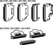
MELSEC Q Series / iQ I/O Wiring Connectors
For the modules listed in the preceding I/O module sections, where connection type is given as “FCN” or “D-sub”, use the following connectors:
|
Model Number |
Certification |
Number of Pins |
Wiring Type |
Connector Type |
Stocked Item |
|
A6CON1 |
UL • cUL |
40 |
Solder |
FCN |
S |
|
A6CON2 |
UL • cUL |
40 |
Crimp |
FCN |
S |
|
A6CON3 |
UL • cUL |
40 |
IDC |
FCN |
S |
|
A6CON1E |
UL • cUL |
37 |
Solder |
D-Sub |
S |
|
A6CON2E |
UL • cUL |
37 |
Crimp |
D-Sub |
- |
|
A6CON3E |
UL • cUL |
37 |
IDC |
D-Sub |
- |
|
A6CON4 |
- |
40 |
Solder |
FCN |
- |
Note: A6CON4 has a bidirectional cable clamp which allows installation depth to be reduced.
MELSEC Q Series / iQ Remote Terminal Blocks
For QXx1, QXx2, QYx1 and QYx2 type I/O modules, the following remote terminal blocks can be used to make I/O connections.
Connector / Terminal Block Converter Modules
|
Model Number |
Details |
Dimensions (W x H x D) |
Applicable Models |
Stocked Item |
|
A6TBXY36 |
32 point terminal block (standard type) |
120 x 78.5 x 52 |
QX41, QX41-S1, QX42, QX42-S1, QY41P, QY42P, QH42P, QX41Y41P LY41NT1P, LY42NT1P, LY41PT1P, LY42PT1P |
S |
|
A6TBXY54 |
32 point terminal block (2-wire type) |
155 x 78.5 x 52 |
- |
|
|
A6TBX70 |
32 point terminal block (3-wire type) |
190 x 78.5 x 52 |
QX41, QX41-S1, QX42, QX42-S1, QH42P, QX41Y41P |
- |
|
A6TBX36-E |
For source type input modules (standard type) |
120 x 78.5 x 52 |
QX81 |
S |
|
A6TBY36-E |
For source type output modules (standard type) |
120 x 78.5 x 52 |
QY81P |
S |
|
A6TBX54-E |
For source type input modules (2-wire type) |
155 x 78.5 x 52 |
QX81 |
- |
|
A6TBY54-E |
For source type output modules (2-wire type) |
155 x 78.5 x 52 |
QY81P |
- |
|
A6TBX70-E |
For source type input modules (3-wire type) |
190 x 78.5 x 52 |
QX81 |
- |
MELSEC Q Series / iQ Remote Terminal Block Cables
Use the following cables to make connections between Q Series / iQ I/O modules and the terminal blocks listed above.
|
Model Number |
Details |
Weight (kg) |
Applicable Models |
Stocked Item |
|
AC05TB |
0.5m (19.69 in), for sink modules |
0.17 |
A6TBXY36, A6TBXY54, A6TBX70 |
S |
|
AC10TB |
1 m (39.37 in), for sink modules |
0.23 |
||
|
AC20TB |
2 m (78.74 in), for sink modules |
0.37 |
||
|
AC30TB |
3 m (118.11 in), for sink modules |
0.51 |
||
|
AC50TB |
5 m (196.85 in), for sink modules |
0.76 |
||
|
AC80TB |
8 m (314.96 in), for sink modules (common current not exceeding 0.5A) |
1.2 |
- |
|
|
AC100TB |
10 m (393.7 in), for sink modules (common current not exceeding 0.5A) |
1.5 |
- |
|
|
AC05TB-E |
0.5m (19.69 in), for source modules |
0.17 |
A6TBX36-E, A6TBY36-E, A6TBX54-E, A6TBY54-E, A6TBX70-E |
S |
|
AC10TB-E |
1 m (39.37 in), for source modules |
0.23 |
||
|
AC20TB-E |
2 m (78.74 in), for source modules |
0.37 |
||
|
AC30TB-E |
3 m (118.11 in), for source modules |
0.51 |
||
|
AC50TB-E |
5 m (196.85 in), for source modules |
0.76 |
- |
Notes:
- “-E” cables use DSUB connectors, non “-E” cables use FCN connectors.
- The number of connectable I/O points is 32 for all connector/terminal block convertor modules. Two connector/terminal block converter modules and two cables for connector/terminal block converter modules are required for 64-point I/O modules.
Mitsubishi Q Series PLC
Features Include:
-
Spans a range of CPU types from small/medium systems, to complex networked systems handling tens of thousands of I/O, addressing the needs of all applications.
-
Embraces contemporary technologies such as high speed Ethernet, open systems and Internet capabilities, to reduce lifecycle costs via remote system management & maintenance.
-
Increases productivity throughout a system life cycle of design, implementation and maintenance by offering a range of capabilities that allow more to be achieved in less time.
-
Multiple CPU capability adds open ended system performance and flexibility.
-
Multiple program capability allows concurrent development, code reuse, better program organization and faster troubleshooting for less downtime.
-
Multiple access to the system allows many technicians to work simultaneously for faster system debugging and maintenance.
-
High productivity GX Developer programming tools permit designers to concentrate on the automation of their system, not the configuration of the controller.
-
Networking & communication options distribute Q Series systems over wide areas while reducing wiring costs.
-
Sequence CPUs can also address process applications by means of built-in PID capabilities.
-
Extremely compact package saves panel costs.
-
Certified bu UL, cUL, CE as indicated and DNV, ABS, RINA, LR & NK shipping approvals for all Q Series.
Products
Product Overview & Configuration
CPUs & Base Units
Power Supplies
Digital I/O Modules & Terminal Blocks
Analog I/O Modules
Temperature Control & Thermocouple Modules
Positioning & High-Speed Processing Modules
Communications Modules
MES
Accessories
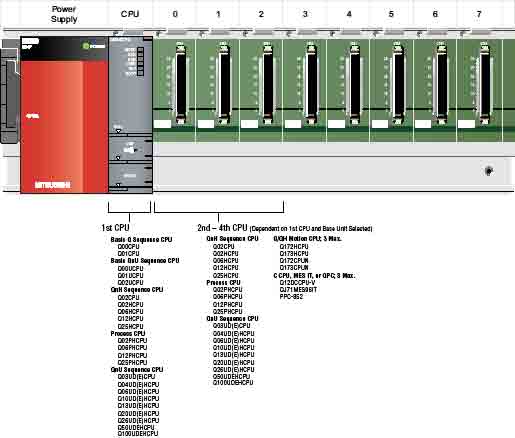
Mitsubishi PLC Overview & Configuration
Q Series Standard and Slim-type Base Units: Q_B and Q_SB
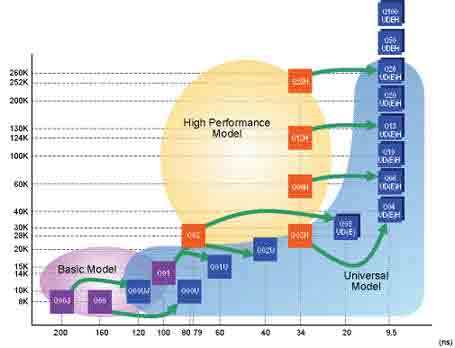
Q Series Migration Path
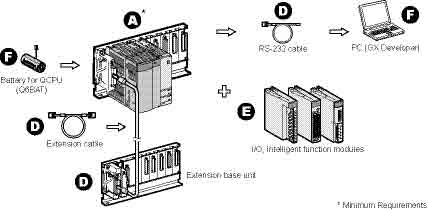
Q Series Integrated System Configuration (Q00UJCPU/Q00UJCPU-S8)
Q Series Multiple CPU System Configuration
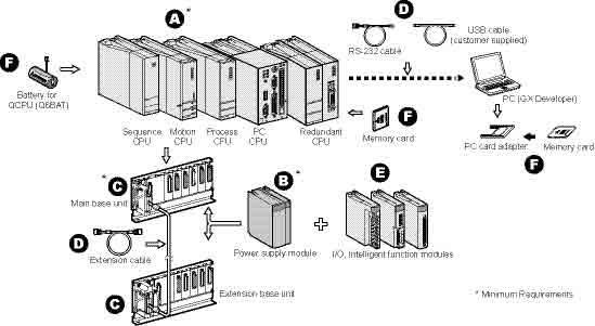
A. Q Series CPUs
B. Q Series Standard Base Units
C. Q Series Power Supply Modules
D. Q Series Extension Base Units and Cables
E. Q Series I/O and Intelligent Function Modules
• Digital I/O Modules and Terminal Blocks
• Analog I/O Modules
• Temperature Input and Control Modules
• High-Speed Input, Positioning Modules and Motion Control
• Serial Communication and Networking Modules
- CPU types ranging from small/medium systems, to complex networked systems with tens of thousands of I/O
- Reduced lifecycle costs via remote system management and maintenance
- Redundant CPU capability available for hot-backup of critical systems
- Multiple CPU capability (up to 4 CPUs) adding open ended system performance and flexibility
- Multiple programs allowing concurrent development, code reuse, better program organization and faster troubleshooting for less downtime
- Multiple simultaneous access to the system allowing for faster system debugging and maintenance
- Networking & communication options distribute Q Series systems over wide areas while reducing wiring costs
- Sequence CPUs can also address process applications by means of built-in PID capabilities
- Extremely compact package saves panel costs
- Certified by UL, cUL, CE (as indicated), as well as DNV, ABS, RINA, BV, LR and NK shipping approvals for all Q Series products
Mitsubihi Power Supplies
MELSEC Q Series / iQ Power Supply Modules
Power supply modules always fit on the left hand end of a rack. All base racks (Q3_B) must include a power supply, as do powered extension racks (Q6_(R)B). We offer PSU to address worldwide AC voltage standards and DC power.
|
Model Number |
Q61P |
Q61P-D |
Q62P |
Q63P |
Q64PN |
Q63RP |
Q64RP |
|
|
Stocked Item |
S |
- |
S |
S |
S |
- |
- |
|
|
Certification |
UL • cUL • CE |
UL • cUL • CE |
UL • cUL • CE |
UL • cUL • CE |
UL • cUL • CE |
- |
- |
|
|
Applicable Base Units |
Q3_DB, Q3_B, Q6_B |
Q3_RB, Q6_RB |
||||||
|
Input Power Supply |
100-240VAC +10%/-15% |
100-240VAC +10%/-15% |
24VDC +10%/-15% |
100-240VAC (+10%/-15%) |
24VDC +30%/-35% |
100 to 120VAC/ 200 to 240VAC (+10%/ -15%) |
||
|
Input Frequency |
50/60Hz ±3Hz |
- |
50/60 Hz ±5% |
50/60 Hz ±5% |
50/60 Hz ±5% |
|||
|
Input Voltage Distortion Factor |
5% or less |
- |
Within 5% |
Within 5% |
Within 5% |
|||
|
Max. Input Apparent Power |
105VA |
- |
160 VA |
65W |
160VA |
|||
|
Inrush Current |
20A within 8ms |
100A within 1ms |
20A within 8 ms |
150A within 1ms |
20A within 8ms |
|||
|
Rated Output Current |
5VDC |
6A |
3A |
6A |
8.5A |
8.5A |
8.5A |
|
|
24VDC |
- |
0.6A |
- |
- |
- |
- |
||
|
External Output Voltage |
- |
24VDC ±10% |
- |
- |
- |
- |
||
|
Permissible Instantaneous Power Failure Time |
Within 20ms |
Within 20ms |
Within 10ms |
Within 20ms |
Within 10ms |
Within 20ms |
||
|
Operation Indication |
LED indication (lit at 5VDC output) |
LED indication and power light |
LED indication (lit at 5VDC output) |
LED indication (Normal operation: ON (green) Error: OFF (red)) |
||||
|
Weight (kg) |
0.31 |
0.39 |
0.33 |
0.40 |
0.60 |
0.47 |
||
|
Base Unit PSU Slots Occupied |
1 |
2 |
||||||
Published in
Projects
Advantech Industrial Automation


Published in
Projects